
With the mass efforts building in the Electron Hall this year, many components of the electron linear accelerator (e-linac) are in position and being readied for operation. This fall, the key milestone is to accelerate electron beam through the e-linac; a crucial step to realizing this is to power up the injector and accelerator cryomodules along with the SRF cavities inside, plus all the water-cooling, cables and controls to bring this piece to life!
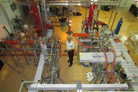
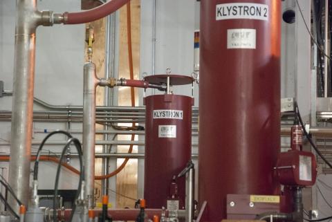
As illustrated in previous articles on the meticulous construction and commissioning of ARIEL, there are many components within the e-linac that are highly technical and specialized—and of course, the e-linac needs an equally specialized and sophisticated power system. This is the high-power radiofrequency system (HPRF System). It includes two high voltage power supplies (HVPS, see second photo), two high power continuous wave (CW) klystrons, wave-guides, and cooling system (top photo). The klystrons (third photo) are radiowave amplifiers and transmitters.
In order to accelerate beam to optimal frequency, the e-linac employs superconducting niobium multi-cell cavities. These cavities operate at 2 degrees Kelvin and use 1.3 GHz as the radiofrequency (RF) source. One injector cryomodule and one accelerating cryomodule bring the energy and beam power of the e-linac to 30 MeV and 300 kW, respectively; a third cryomodule that would be added in the ARIEL-II project could raise the energy to 50 MeV.
To adequately power up these components, the HPRF System uses high power CW klystrons, which operate at 1.3 GHz. The klystrons were purchased from CPI, Microwave Power Products, in California, USA and the high voltage power supplies–which provide all the required 60,0000 Volts DC power for the klystron –were purchased from AMPEGON in Switzerland. These pieces of equipment are rare commodities and were specifically designed and procured to meet the high power demand of the e-linac. The 290 kW CW klystron was developed in collaboration with HZB (Helmholtz-Zentrum Berlin). The klystron amplifier gain is so great that less than 10 Watts input is needed to produce the full rated output power of 290 kW.
The high power RF system – aside from the klystrons and the high voltage power supplies – also consists of waveguide systems that connect the klystrons to the superconducting cavities. The waveguides are analogous to fibre-optic cables; they transmit radio-waves with near-zero loss. The water-cooling system was of utmost importance since the total power to be cooled is close to 1000 kW.
The first klystron was received at TRIUMF on March 21, 2013. Testing of the klystron requires the high voltage power supply and therefore the tests were completed once the HPVS system was commissioned. The first high voltage power supply (HVPS) was received at TRIUMF on August 13, 2013 and was commissioned on October 25, 2013. The second klystron was received on March 24, 2014 and commissioned within five months. The second HVPS was received on May 28, 2014 and commissioned on August 22, 2014. The RF system was commissioned for beam test with the injector cryomodule in May 2014 and the second RF system is getting ready for beam test with accelerator cryomodule in September 2014. The two klystrons were installed and commissioned by the TRIUMF staff thus gaining expert knowledge and training of these highly sophisticated high voltage power supplies.
The installation, testing and commissioning of the high power RF system was possible due to enormous support and help from various groups at TRIUMF. The following departments were particularly involved throughout the project:
- Finance Department
- Design & Manufacturing Department
- Electrical Services Department
- Electronics & Controls Department
- Mechanical Services Department
- Project Engineering Department
- RF/SRF Department
A special note of acknowledgement.
There were many special challenges throughout the course of this project. One of the most difficult undertakings was to conceive the design of the complete system on 3D Solid Works to ensure all rigid waveguides and components precisely connect the klystron to the cryomodules. Another challenging task was to flame-solder the segments of 8 inch wide copper ground from the high voltage power supply (located on the roof of the e-hall) to the klystron (in e-hall). Connecting the high voltage DC power supply to the 12.5 kV AC switchgear and powering it for the first time was nerve racking. The high inrush current made the 500 MeV cyclotron trip a few times. During the initial RF test of the klystron, the terminating waveguide load, a vital component failed and was returned to the manufacturer for warranty repair. The high power RF project spanned a period of three years, starting with conceptual design of HPRF, specification of the devices, tendering, procuring, receiving, installing, commissioning and eventually delivering RF to the superconducting cavities.
Congratulations to all!
Top photo: Amiya Mitra stands in the e-hall between the two klystrons, wave guides, and cooling system. Second photo:The high power voltage supply on the e-hall roof.Third photo: A close-up of the two klystrons.
–Prepared by Amiya Mitra, RF Group Leader, and Melissa Baluk, Communications Coordinator